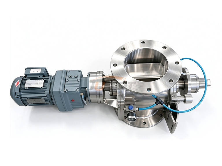
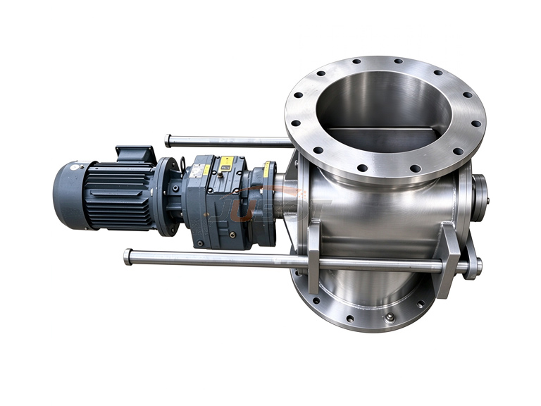
Product Overview
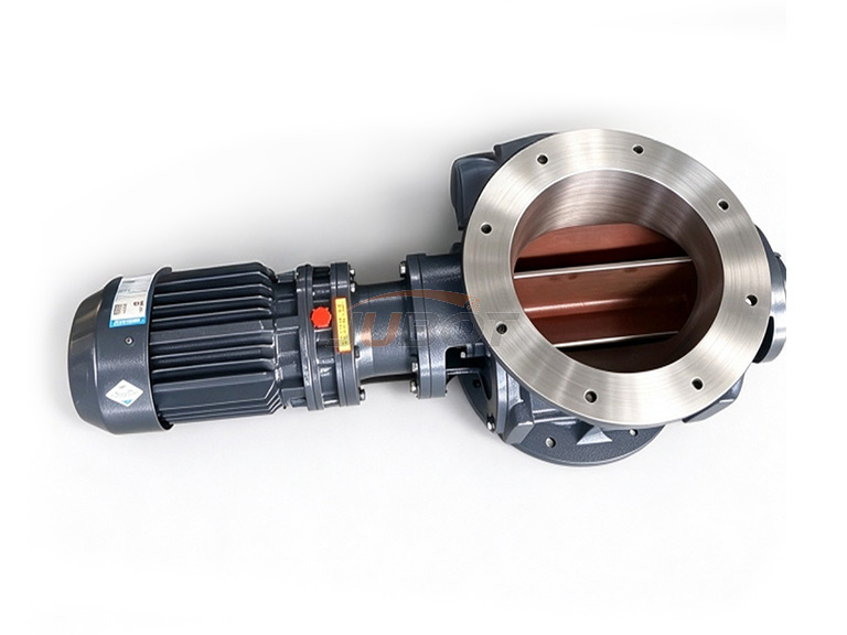
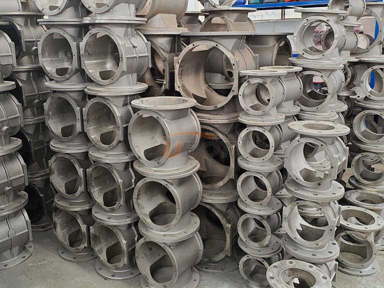
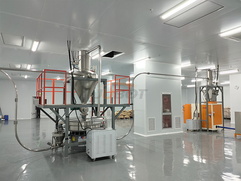
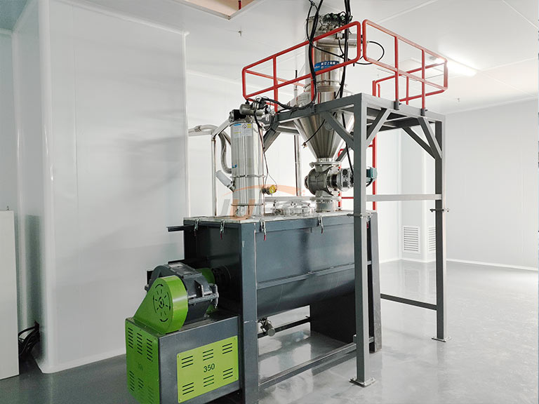
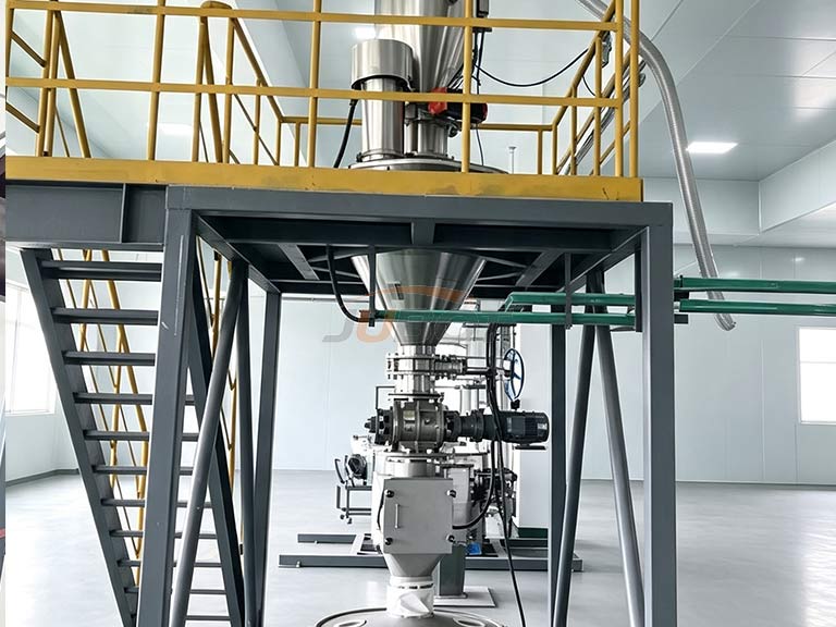
The Rotary Valves & Airlocks is a precision-cast feeding device designed to meet demanding industrial needs. It is widely used for silo discharging, positive/negative pressure pneumatic conveying, and dust collector discharge systems.
How It Works
Material enters the valve and is transferred smoothly by the rotating rotor, providing precise, uniform, and continuous feeding. Meanwhile, the precision-machined rotor acts as an air seal, preventing pressure leakage between the upper and lower chambers during pneumatic conveying. It also serves as a critical component in dust collection systems.
Main Structure
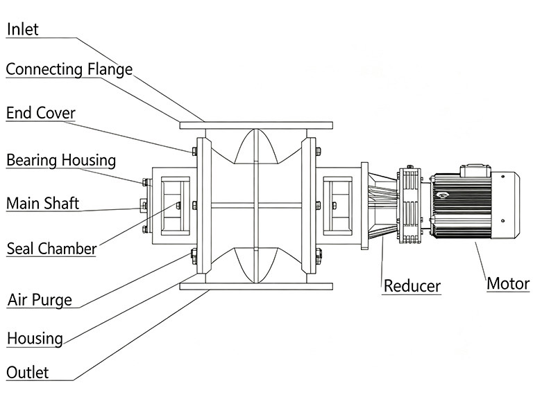
The Rotary Valves & Airlocks is mainly composed of the housing, end covers, rotor shaft, seal chamber, bearing housing, air purge system, gear reducer, motor, inlet, and outlet. This equipment is designed for quantitative, uniform, and continuous feeding.
Working Principle
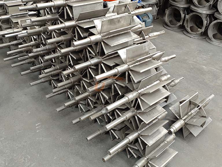
Upon startup of the Rotary Valves & Airlocks, material falls by gravity and fills the spaces between the rotor blades, and is then discharged at the lower side as the rotor rotates.
Applicable Materials & Industries
- Materials: Dry powders and small granular materials.
- Industries: Ceramics, pharmaceuticals, food processing, plastics, mining, pigments, new energy materials, and more.
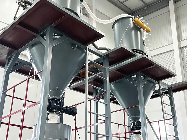
Customization
Drive Options: Explosion-proof motors, variable frequency drives (VFD/VFD speed control), and custom gearboxes available upon request.
Material & Coatings: High-temperature resistant alloys, corrosion-resistant materials, stainless steel, nylon, polyurethane lining, or Teflon (PTFE) coating.
Quick-Clean Slide Rail Type: Designed for easy disassembly and rapid cleaning.
Pressure-Balanced Type: Ideal for lightweight materials.
Key Features
Superior air-sealing performance;
Smooth, uniform, and continuous feeding;
Low noise and minimal vibration;
High wear resistance and long service life;
Low maintenance and high reliability;
Specification Table
| No. | Model | Power (kW) | Installation Dimensions (mm) | Rotational Speed (r/min) | Drawing No. | Remarks | |||||||
| Model | Volume (L) | ΦA | ΦB | ΦC | N*ΦG | H | L1 | L2 | |||||
| 1 | DN150 Standard | 2L | 0.75 | 150 | 200 | 240 | 8*Φ12 | 245 | 240 | 930 | 35 | A | |
| 2 | DN200 Standard | 6L | 0.75 | 200 | 260 | 302 | 8*Φ14 | 310 | 560 | 630 | 35 | A | |
| 3 | DN250 Standard | 10L | 1.5 | 250 | 300 | 350 | 8*Φ14 | 360 | 360 | 680 | 35 | A | |
| 4 | DN300 Standard | 14L | 2.2 | 300 | 400 | 445 | 12*Φ22 | 400 | 780 | 780 | 24 | B | |
| 5 | DN150 Reinforced | 4L | 0.75 | 150 | 240 | 285 | 8*Φ22 | 320 | 580 | 560 | 24 | B | |
| 6 | DN200 Reinforced | 8L | 1.5 | 200 | 295 | 340 | 8*Φ22 | 370 | 680 | 650 | 24 | B | |
| 7 | DN250 Reinforced | 12L | 1.5 | 250 | 350 | 395 | 12*Φ22 | 408 | 720 | 650 | 24 | B | |
| 8 | DN300 Reinforced | 24L | 3 | 300 | 400 | 445 | 12*Φ22 | 480 | 820 | 890 | 24 | B | |
| Remarks: L1 and L2 shall be subject to actual dimensions due to different motor configurations. | |||||||||||||